ELEC 244 Lab 2
A major characteristic of Op-Amps is their Slew Rate. The Slew Rate of an Op-Amp is the maximum rate of change of the output voltage with respect to time. I.e.
Slew Rate = max(
dVout
dt
)
Why Slew Rate is Important
Slew Rate is an important parameter in circuit design. If your circuit operates at high frequencies, you need to use an Op-Amp whose Slew Rate is rated above the frequency and amplitude you plan to use. For sinusoidal signals, your signal must satisfy the following condition to avoid Sine Wave Distortion:
Slew Rate ≥ 2πfVp
Why Op-Amps have a Slew Rate
Slew Rate can be understood by looking at the internal circuitry of the Op-Amp. If you look at the Functional Block Diagram of the LM741, you will notice that there is a 30pF capacitor (C1) within the circuit. This capacitor is known as the Compensation Capacitor.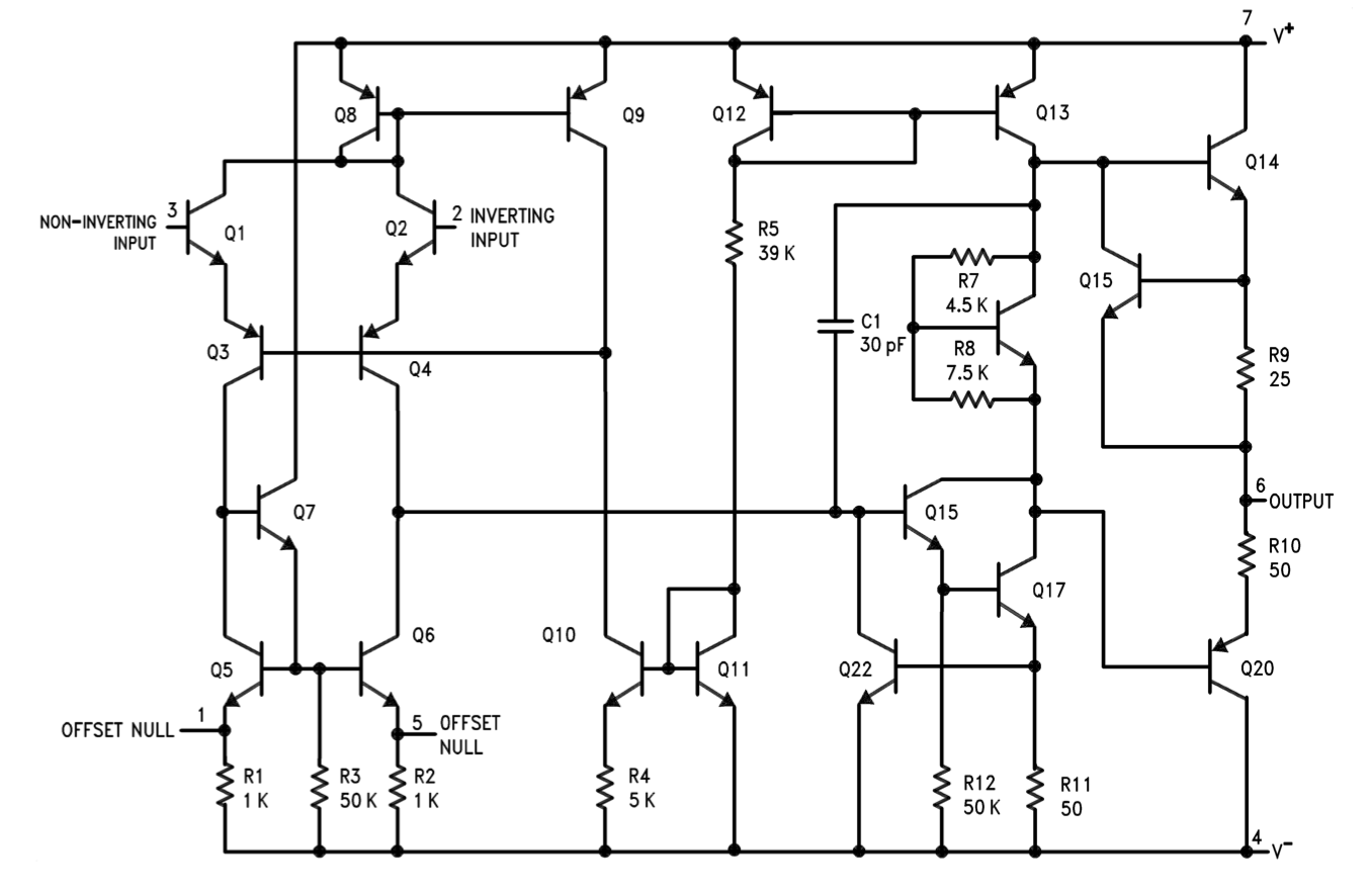
TI LM741 Datasheet: https://www.ti.com/lit/ds/symlink/lm741.pdf
This capacitor affects the area around it, and is one of the main causes of Slewing. If you have not buried the trauma of ELEC 241 or PHYS 102, you’ll remember that the current of a capacitor is given by:
I = C
dV
dt
dV
dt
=
I
C
dt
=
C
I
dV
Δt
=
CΔV
I
ELEC244_LAB2_SOLUTION_S26.pdf