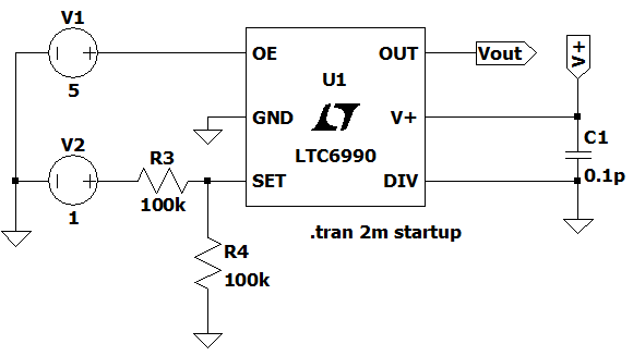
LTC6990 Voltage Controlled Oscillator
The VCO circuit shown here is based off of the LTC6990 IC from Analog Devices. The topology of this specific VCO with it's component values allows for a frequency range of ~50kHz to 1000kHz. The frequency is controlled by an input voltage ranging from 0V to 2V. This circuit was simulated in LTSpice at various control voltages to determine the output frequency. The resulting waveforms are: Vctrl = 0V, Vctrl = 1V, Vctrl = 2V.
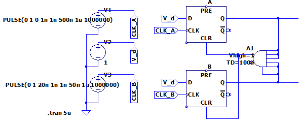
Phase Detector Circuit
This phase detector takes in two square wave inputs and outputs a set of short pulses where the two inputs differ in phase. As shown in the circuit schematic, one of the square wave inputs is delayed behind the other, thus allowing the phase detector circuit to output the different in phase as a pulse train. This circuit was simulated in LTSpice to verify the circuit works as intended, and the simulated wave form is as follows: Phase Detector Output.