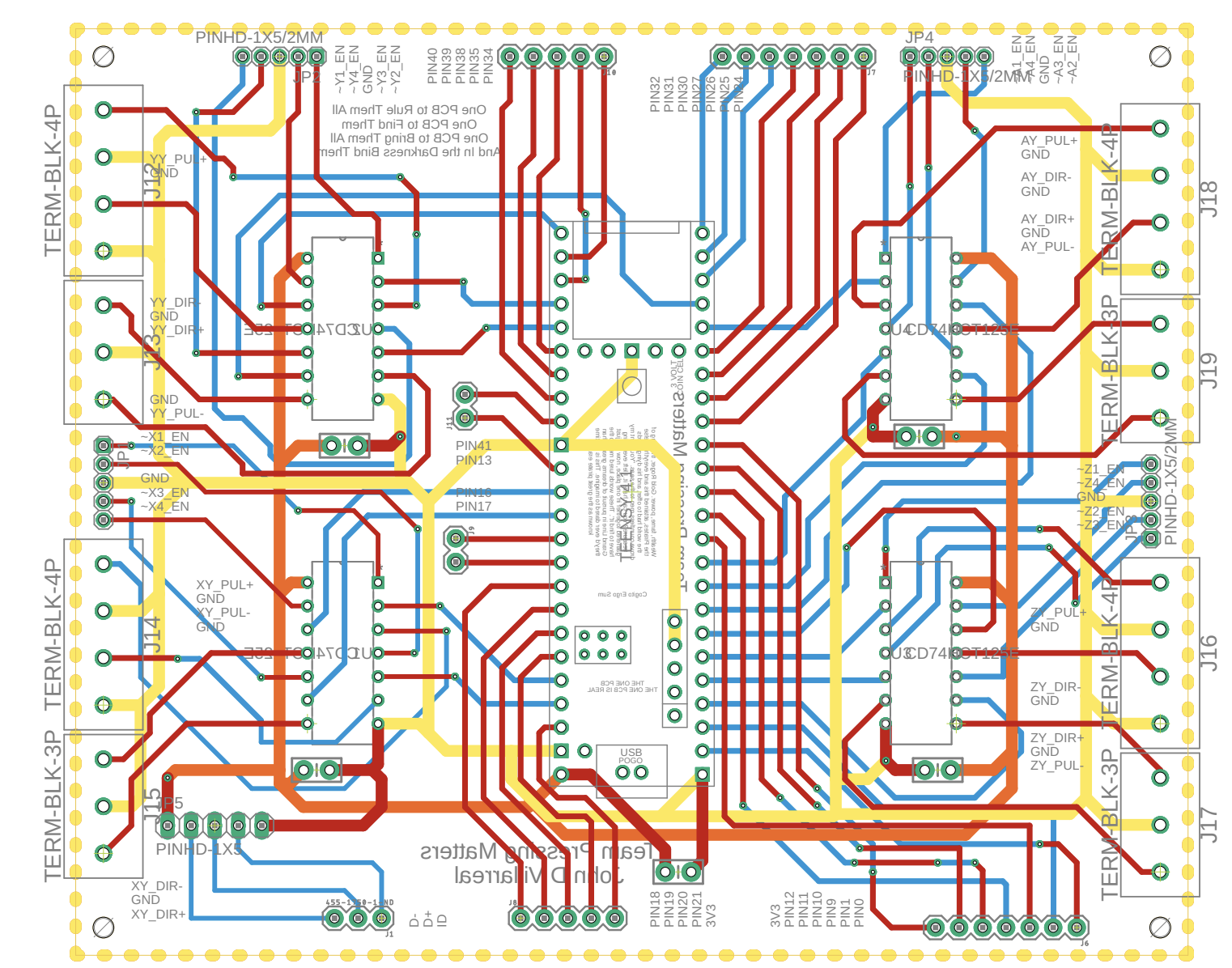
Automated Biosensor Printer Printed Circuit Board Design Retrospective
For my Senior Design project, my team and I created the Automated Biosensor Printer. I was responsible for designing the PCB utizing EAGLE. This PCB was my first major project that involved multiple layers, components, and complex routing. Over the course of the project, I learned a lot about PCB design and important considerations that need to take place; however, I now want to reflect on the design choices I made and how I would improve my future designs. To do this, I am utilizing HyperLynx to simulate the signal integrity of some of the high-speed signals on the board. By doing this, I hope to be able to better understand and design high-speed PCBs.Click on this link to view my analysis
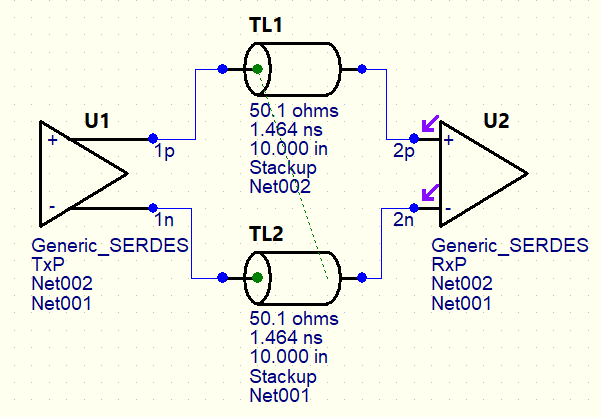
Eye Diagrams and Jitter (and why they need eye drops)
For this mini-project, I designed a simple high-speed transmission line circuit in HyperLynx, and simulated an eye diagram at the receiver at the end of the line. My main goal was to familiarize myself with HyperLynx and simulating signal integrity with Eye Diagrams. I first simulated the circuit with no added jitter. Then, I added two types of jitter as I simulated the circuit. The first simulation comprised of added Gaussian jitter, and the second simulation had both Gaussian and Sinusoidal jitter. The resulting eye diagrams are: No Added Jitter, Added Gaussian Jitter, Added Gaussian and Sinusoidal Jitter.